Galaxie Brake Conversion
-
by Tom Volpone
I’ll write down from memory on the conversion of power
brakes on a 66-68 Galaxie. This is
to convert a 7 Litre or power disk brake car with the
Kelsey Hayes 4 piston caliper assembly to a 77-79 T-bird front disk brake
system. The benefits for doing it are
that parts for the TBird system are much easier to
obtain and are cost friendly. This
conversion is possible on earlier year Galaxies, and those with drum brakes,
but a couple of other items are required to convert which would include
addition of a proportioning valve and new disk brake master cylinder. If this conversion is considered for those
cars, upgrading to a dual circuit brake system would be beneficial, which would
require a new dual master cylinder, replumbing the brake
lines to separate the front & rear circuits and addition of aforementioned
proportioning valve.
In my conversion, I obtained the front spindle assemblies
from a 77 Tbird at a local yard. The spindles were in decent shape, and the
yard only charged me $40. The yard
torched the upper and lower control arms and tie rod ends to extract them from
the donor. Other spindles that could be
used are from any 77-79 Tbird, Ranchero, Cougar, or
LTDII. These all have the 4.5 x 5 bolt
pattern for the wheels. Additionally,
you’ll want to obtain is the actual wheels from the donor, as the center
hub on the spindle assemblies are larger than the Galaxie’s
making the Galaxie wheels unusable. You might want to grab 3 and use the extra as
your spare tire. It will bolt right up
to the rear axle, though there will be space between the center of the wheel
and the hub assembly, but that isn't of any concern when using it temporary in
a spare situation. You could also pirate
the anti-sway bar from the Tbird, it is 1-1/8
diameter and much more robust that the stock Galaxie
¾ bar. It bolts right in, though you’d
need new frame mount bushings and mounts.
It would make the anti-sway bar links angle backwards which is usable
this way but you can also reposition the frame brackets by drilling new holes
and moving the J-nuts that hold them in place.
I did not extract the master cylinder, brake booster or
prop/distribution valve from the donor, as my 7 Litre
is already a disk brake car and I desired to retain the original single master
cylinder for originality appearance. The
methods below detail this conversion.

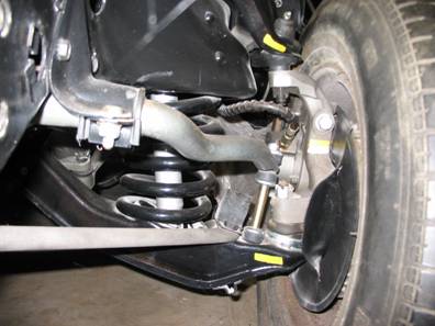
The detail in starting the conversion begins with first
lifting up the front of the car and set it on jackstands,
preferably under the front torque boxes which will keep them out of the
way. Raise the car up a good height, as
you will need it to swing the lower control arms all the way down to remove the
springs. Remove the front wheels from
your Galaxie.
Open up the brake bleeder from the caliper and let the small amount of
fluid out that will inevitably spill, then take a 3/8 brake wrench and separate
the brake hose from the frame mount. A
regular 3/8 wrench can work, but it risks rounding out the nut a
s i
t only grab
s i
t
on two sides, and it may be a tough extraction.
Use whatever method, as you won't be reusing this or the brake
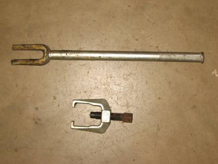
hose. You can cut the hose if you’d like. Next you’ll remove the cotter pin and nut
that attaches the outer tie rod end to the spindle. You will most likely need a tie rod
separator, which is a “C” clamp looking device that will hold the spindle ring
while it presses the stud out. You can
loan one from Autozone for free (you pay for the
tool, but when you return it you get the money back). You’ll need to detach the strut rod from the
lower control arms. They are attached
with two bolts. The nuts are captured
under the arm, but sometimes they come loose and you’ll need to hold them with
a deep socketed wrench to remove. Next remove the bottom of the anti-sway bar
links, which connect the anti-sway bar to the lower control arm. It is held in place by a nut at the bottom of
the arm. Once the links are separated,
you can remove the shock absorbers.
There are two nuts at the bottom and one nut at the top. This may be a challenge depending on how long
they have been in your car. The bottom
bolts may break, and the top one can be a test as the shock will want to rotate
as you turn the nuts. After you get them
out you’ll be separating the lower ball joint.
This will free the spring, so here is where caution is to be
practiced. The spring is loaded with
energy and can be a projectile if allowed to separate freely. To safely do this, first run a heavy chain
through the center of the spring and make a generous loop around through the
upper & lower control arms. This
will be the safety net that keeps the spring from launching. The chain should be secured on both ends
together, and be generou
s i
n length,
the idea is to contain the spring during separation of the control arm from the
spindle. Next you’ll take a pickle fork,
which is a two pronged fork tool that has ramped teeth which are placed on
either side of the ball joint stud.
You’ll have to wedge it under the grease boot and position it so that
when it is hammered into place it will straddle the ball joint stud. Then, you’ll get to hammer on the end of the
fork until the joint separates. You
might have to exert some forceful blows to get the separation. This will happen in a sudden manner, almost
violent which is why you need that safety chain in place. Now you can remove the chain and the control
arm will swing down out of the way and drop the spring out. You might have to lift up on the control arm
with your floor jack to separate & remove the chain if you made your chain
loop too small and it is bound in place.
You can remove the upper ball joint nut.
If you wish to replace your ball joints, you can make it easier by
grinding off the three rivets on the top of the control arm that hold it in
place and allow the spindle with joint to separate from the upper control
arm. I recommend this method, due both
because a 40 year old car could use new ball joints most likely, and the method
to separate the upper ball joint is difficult.
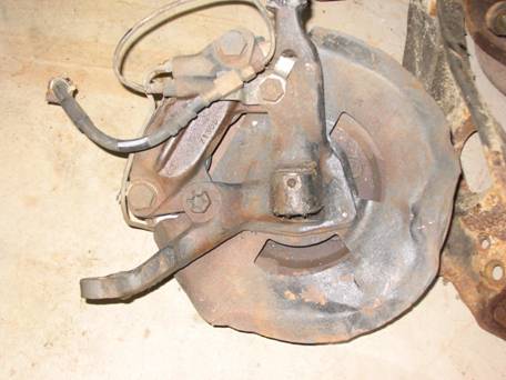
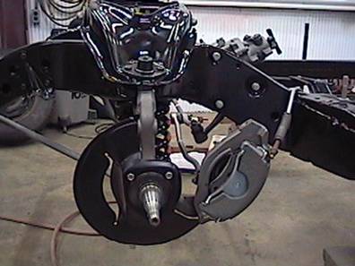
When I removed my assembly, I took the upper control arm off of the
chassis, then had to make a tool using a spacer and long bolts to press the old
ball joint out of the spindle. If you
grind off the three rivets and replace with a new ball joint, you won't have to
extract it from the old spindle. The spindle assembly is heavy, so take care a
s i
t comes apart.
You could have removed the caliper and rotor if you wanted and make this
lighter to remove.

|
Upper ball joint replacement
|
|
I will not get into refurbishing the spindle assemblies from
the Tbird here.
It is assumed that you have cleaned them up, made any necessary
refurbishing such as new bearings, rotor replacement or turning, new pads,
etc. I’m also assuming you have
installed your new ball joints and control arm bushing
s
i
f you chose to do so.
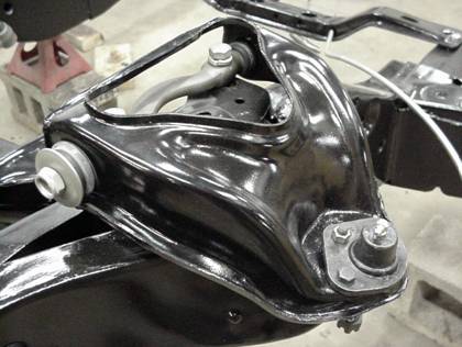
It is best to install the spindle by itself, meaning you
don’t have the caliper or rotor attached.
This means you don’t have to muscle up the entire assembly to position
the upper ball joint to the upper spindle eyelet. Position the upper ball joint stud into the
eyelet and start the castle nut. Torque
the nut to 60 - 90 lbs-feet and install the cotter pin. You are ready to install the spring. There are a couple ways to safely install the
spring. The spring is very thick and has
a lot of energy when compressed. Still
assuming that your engine i
s i
n the
car, you can use the weight of the car to help compress the spring. If you are doing a restoration and you don’t
have your engine/vehicle assembled you will have to compress the spring externally
before installing it. You can do this by
taking the spring to a place that compresses and bands them, or getting an
inner-jaw spring compressor and compressing it with that. Spring compressors work, but since the spring
is so heavy duty you’ll tax it good, most likely needing to use an impact gun
to get it compressed enough to fit in (even though the instructions say not to
use an impact gun). I did it this way,
and it destroyed the spring compressor a
s i
t
galled the threads on it (I did my work on a bare chassis). Keep in mind that if you have it shrunk down
in a spring compressor there’s enough energy there to fire a cannonball some
impressive distance, so be careful and use a good robust compressor. The method I will continue with is a
s i
f your car is all in one piece with the engine
installed.
The control arm mounting perches are indexed so that the
spring will seat flush in the pockets.
By this I mean there are provisions on the upper and lower control arms
to position the ends of the springs so that they sit flush when installed. The springs are not flat on the ends. When you lift the spring in place you will
have to find the correct orientation so that the spring end is positioned in
the pocket index. You will have to lift
the spring and locate it in the upper pocket, then lift up the lower control
arm and position it so that the spring will seat in the pocket when it is
compressed. The spring will be straight,
but the bottom arm will not line up flush with it due to the angle of the arm. Place your floor jack under the arm such that
you will have access to the lower ball joint, and use it to hold the arm in
position while you make sure your spring is aligned properly. For safety, you can thread your chain back
through the spring and arms and tie the chain ends together leaving a generous
loop. Now, you will lift up the lower
control arm with the floor jack. The arm
will swing up into place. Keep an eye on
your spring end alignment, the spring will compress as you lift. Align the lower ball joint stud into the
spindle a
s i
t gets close and pres
s i
t up into place, then thread the castle nut
on. Torque the nut to xx lb-feet and
install the cotter pin. You can lower
the floor jack and pull it out of your way, and remove the chain.
Position the outer tie rod in place. The eyelet at the bottom of the new spindle
is about 1/8 inch thicker than the Galaxie’s original
spindle. This will result in the
inability to align the cotter pin through the castle nut, as the nut will not
be able to be tightened far enough due to the spindle thickness. There are two ways to address this: 1. shave the bottom of the castle nut
down. 2. deepen
the slot on the castle nut that will be aligned to the cotter pin hole. You also could have machined the spindle
mount thinner. What I did was after torquing the castle nut to factory specs, I used a file to
lengthen the slot aligning to the cotter pin hole which allowed then the
insertion of the pin. Once you have
selected your method, install the cotter pin after torquing
the castle nut to 35-47 lb-feet. Your
spindle is now in place.
Now you’ll reattached all the peripheral components that you
took apart, including shocks (20-28 lb-feet upper, 8-12 lb-feet lower), strut
rods (70 lb-feet), sway bar links (5-10 lb-feet). You can install the rotor, and position the
caliper in place and tighten. Check the
brake spindle to backing plate bolt torque as well, which should be 80-106
lb-feet.
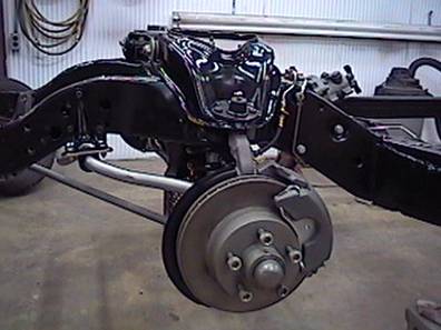
You will install the hoses to the caliper and hardline. I used the
stock TBird hose.
The caliper will position the hose in an awkward looking manner. It will work this way, the alternative is to reposition
the front hardlines and have them exit in a different
place. This would most likely require
new front hardlines I chose to keep the hardlines as they were.
You can now bleed your brakes. Install your front wheels and you’re
done. You’ll note that the 7Litre style
wheels may have trouble fitting over the larger hub covers. You can take a dremel
to the inside lip of the wheel cover center cap. It requires very little grinding to acquire
the necessary spacing. With a little care the grinding is unnoticeable. It is
not often that people inspect the inside of your wheelcovers
at a show. (This is a difficult decision if you are putting NOS wheelcovers on. User
discretion is all I can say). Also
you’ll notice that the air valve on the wheel may not align with the
corresponding hole in the wheelcover. You will need to reposition the hole in the
wheel for the air valve by 45° so that it will allow the lug holes in the wheelcover to line up with the wheel. When you have the front end aligned, use the
77 Tbird specs.